AMD 대규모 Fan-out IOD
개요
AMD EPYC의 chiplet 설계는 코어와 cache를 담은 여러 CCD(Compute Core Die)와 memory·I/O 기능을 모은 IOD(I/O Die)를 하나의 processor package에 조합한다. AMD가 4th Gen EPYC architecture에서 설명하는 hybrid multi-chip 구조는 compute와 I/O의 혁신 경로를 분리하며, EPYC 7002는 최대 64코어·8채널 DDR4·128 PCIe 4.0 lanes, EPYC 9004는 최대 128코어·12채널 DDR5를 제공한다. 5th Gen EPYC 9005는 Zen 5 또는 Zen 5c 기반 chiplet으로 최대 192코어까지 확장된다.
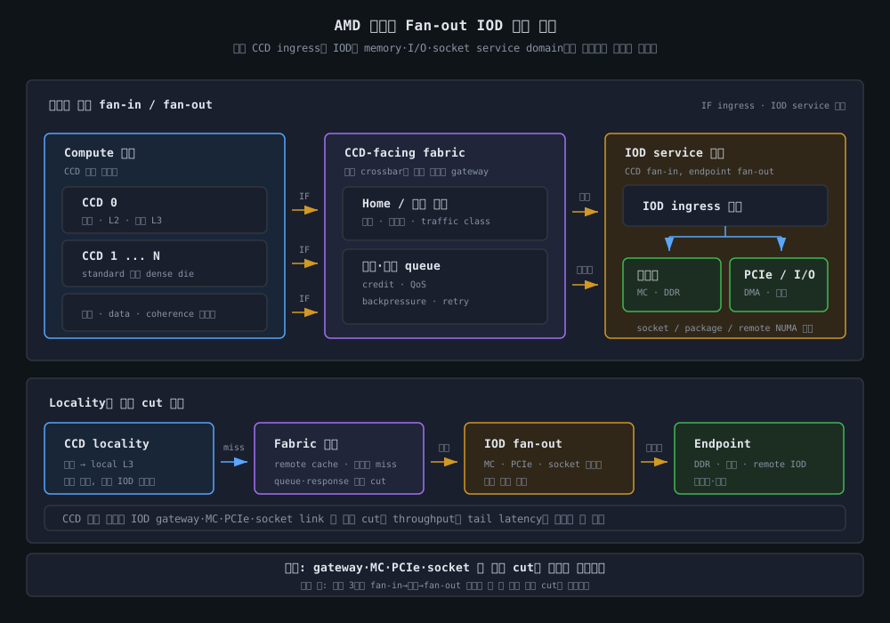
이 문서에서 대규모 Fan-out IOD는 AMD가 모든 제품에 붙인 단일 IP 이름이 아니라, 많은 CCD-facing ingress를 IOD의 memory controller, PCIe와 socket/package service로 집계하고 다시 여러 endpoint로 분기하는 분석 모델을 뜻한다. 실제 IOD 내부의 crossbar, directory, queue 깊이와 link topology는 세대·SKU별 공개 범위가 다르므로, 아래 그림은 공개된 package 기능 경계와 측정 가능한 traffic path를 설명하는 개념도다.
핵심 개념
1. Fan-in과 Fan-out은 서로 다른 병목을 만든다
여러 CCD에서 나온 요청은 CCD 내부 cache lookup을 통과한 뒤 IOD-facing path로 유입된다. IOD는 이 요청을 memory service, PCIe/I/O service, 다른 socket 또는 package endpoint로 보낸다. 따라서 fan-in은 여러 source가 공통 ingress·queue·home service를 공유하는 현상이고, fan-out은 하나의 IOD가 여러 종류의 service endpoint와 외부 경계를 제공하는 현상이다.
| 구간 | 입력 | 출력 | 관찰할 병목 |
|---|---|---|---|
| CCD local domain | 코어의 load/store와 coherence request | local L3 또는 IOD-facing request | L3 경쟁, request injection, local cache miss |
| CCD-facing fabric | 여러 CCD의 request·data·response | IOD ingress 또는 remote coherence service | link utilization, credit stall, response cut |
| IOD ingress | CCD·socket·I/O에서 온 transaction | address/home/class별 service queue | fan-in, arbitration, queue occupancy, backpressure |
| Memory service | read/write와 cache miss | DDR channel·rank·bank | memory-controller queue, channel imbalance, DRAM timing |
| I/O·socket service | PCIe/DMA 또는 remote-socket transaction | device, accelerator, remote IOD | I/O ordering, link retry, DMA interference |
Fan-out은 단순히 1개의 입력이 N개 출력으로 복제된다는 의미가 아니다. 주소와 transaction class에 따라 하나의 목적지를 선택하거나, coherence·write ownership처럼 여러 agent의 응답을 수렴해야 한다. 실제 구현에서는 request, data, snoop, invalidate, acknowledgement가 서로 다른 논리 경로와 buffer를 사용할 수 있다.
2. IOD는 공통 service boundary이지 반드시 하나의 crossbar가 아니다
Central IOD 또는 IOD를 모든 트래픽이 통과하는 단일 blocking crossbar로 그리면 분석이 쉬워 보이지만, 공개 자료만으로 모든 EPYC 세대의 내부 구조를 그렇게 확정할 수는 없다. IOD는 기능적으로 다음 경계를 제공한다.
- Memory-facing boundary: cache miss를 address mapping에 따라 memory controller와 DDR channel로 전달한다.
- I/O-facing boundary: PCIe root complex와 외부 device의 request·completion·DMA 경로를 수용한다.
- Package/socket boundary: 다른 CPU socket, accelerator 또는 coherent endpoint와 연결되는 경계를 제공한다.
- Fabric gateway: CCD에서 유입된 request와 response를 방향·class·flow-control 상태에 따라 분배한다.
- Management/RAS boundary: boot, power, telemetry와 error handling을 compute die만의 경로로 보지 않게 한다.
fan-out IOD라는 표현은 위 기능의 집계 경계를 나타내며, 특정 제품의 내부 arbitration, home hash, directory 위치 또는 queue 수를 주장하지 않는다.
3. CCD 수와 IOD service capacity는 같은 방식으로 늘지 않는다
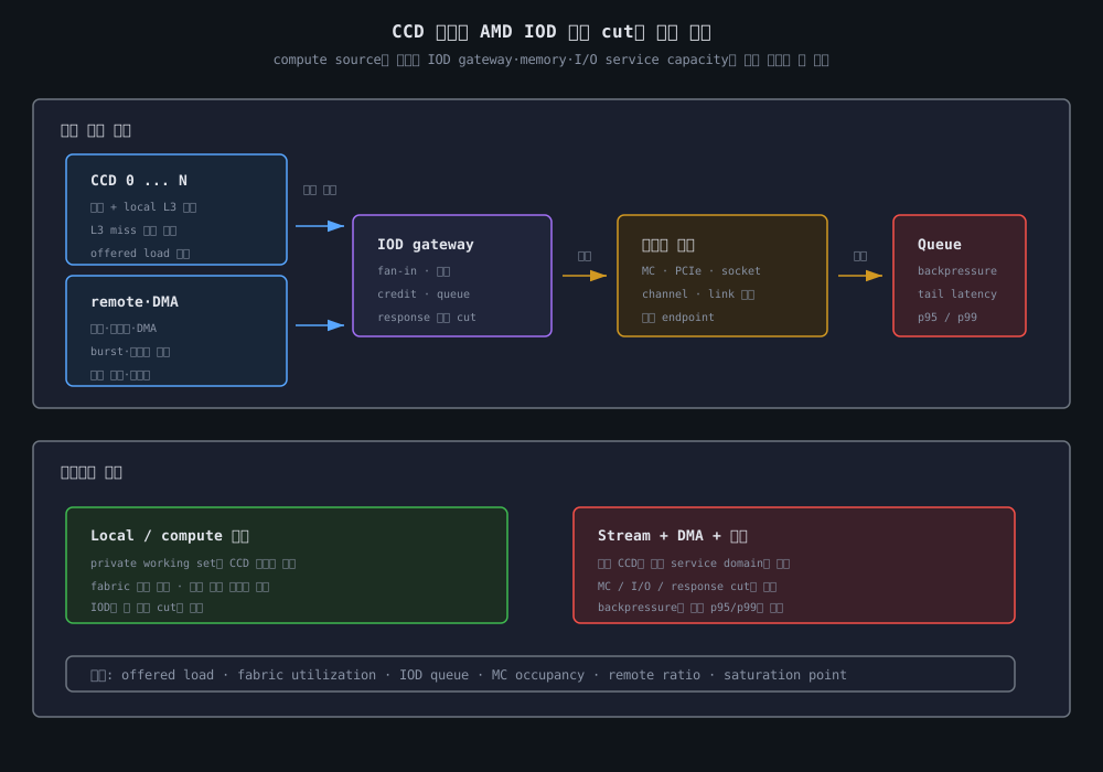
CCD를 추가하면 코어와 cache capacity, request injection source가 늘어난다. 반면 한 socket의 memory channel 수, IOD gateway, PCIe root complex와 socket link는 제품의 정해진 interface budget을 공유한다. 이 비대칭 때문에 compute throughput이 증가해도 memory·I/O traffic의 sustained throughput은 같은 비율로 증가하지 않을 수 있다.
| 자원 | CCD 증가의 효과 | IOD 관점의 주의점 |
|---|---|---|
| Core·private cache | independent compute source 증가 | workload가 실제로 병렬화되어야 함 |
| Shared L3 locality | CCD별 cache group 증가 | remote CCD access에는 추가 fabric·coherence 비용 |
| CCD-facing link | offered load와 response traffic 증가 | 공통 cut과 방향별 link capacity가 상한이 됨 |
| DDR channel | memory endpoint 수는 별도 제품 budget | channel interleave와 controller queue가 hotspot을 결정 |
| PCIe/I/O | DMA·device traffic이 추가됨 | CPU memory traffic과 IOD egress를 공유할 수 있음 |
| Socket link | remote NUMA traffic 가능 | local·remote service와 retry가 tail latency에 영향 |
4. 세대별 공개 범위와 분석 단위
아래 수치는 제품군의 공개 범위다. 하나의 SKU가 표의 모든 maximum 값을 동시에 가지거나, 표의 수치만으로 exact CCD 수와 내부 route를 역산한다는 뜻은 아니다.
| 제품군 | 공개된 대표 범위 | Fan-out IOD 분석 포인트 |
|---|---|---|
| EPYC 7002 / Zen 2 | 최대 64코어, 8채널 DDR4, 128 PCIe 4.0 lanes | 여러 CCD의 request를 I/O die와 DDR4/PCIe service로 집계하는 초기 chiplet 모델 |
| EPYC 7003 / Zen 3 | 최대 64코어, DDR4·PCIe 4 세대 플랫폼 | CCD 내부 unified complex locality와 IOD-facing traffic을 분리 |
| EPYC 9004 / Zen 4·Zen 4c | 최대 128코어, 12채널 DDR5, PCIe Gen5 platform | standard·dense CCD 조합과 12-channel memory service의 공통 cut을 함께 측정 |
| EPYC 9005 / Zen 5·Zen 5c | 최대 192코어, chiplet architecture | core density 증가와 SKU별 IOD·memory·I/O configuration을 따로 확인 |
AMD product page의 core count와 memory channel 수는 capability의 상한 또는 interface 규모를 보여준다. application의 sustained bandwidth는 access pattern, read/write 비율, address interleave, controller scheduling, software placement와 queue 상태를 거친 결과이므로 이 수치를 그대로 fabric bandwidth로 사용하지 않는다.
5. Locality는 CCD, IOD, NUMA 경계를 함께 봐야 한다
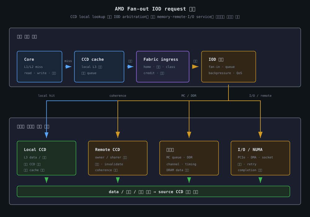
같은 socket 안에서도 요청이 local L3에서 끝나는지, 다른 CCD의 cache line을 찾는지, IOD를 거쳐 DRAM에 가는지에 따라 경로가 달라진다. 두 socket 환경에서는 remote IOD와 socket link가 추가된다.
| 접근 유형 | 대표 경로 | 주요 비용 |
|---|---|---|
| 같은 CCD L3 hit | core → local L3 | cache lookup과 같은 CCD의 contention |
| 다른 CCD cache hit | source CCD → fabric/home → target CCD | remote traversal, coherence와 response queue |
| 같은 socket DRAM | CCD → IOD gateway → MC → DDR | IOD ingress, MC scheduling, DRAM service |
| PCIe DMA | device ↔ IOD ↔ memory | I/O egress, ordering과 CPU memory traffic 경쟁 |
| remote NUMA DRAM | local CCD/IOD → socket link → remote IOD → DDR | remote home, socket link queue와 remote memory |
따라서 local memory라는 표현만 기록하지 말고 thread affinity, NUMA node, NPS 설정, first-touch 또는 explicit memory policy를 함께 기록해야 한다. Linux는 AMD topology에서 package·core·thread와 CCD/die 계층을 CPUID와 firmware 정보로 모델링할 수 있지만, OS가 모든 내부 fabric queue와 physical route를 노출한다는 의미는 아니다.
비교/분석
1. Monolithic I/O와 Fan-out IOD
| 항목 | Monolithic die | CCD + Fan-out IOD | 분석 질문 |
|---|---|---|---|
| compute 확장 | 한 die 안에서 core와 I/O를 함께 확장 | 작은 CCD를 반복 조합하고 IOD가 집계 | die 면적과 package 경계 중 어느 쪽이 먼저 제한되는가? |
| 공정 최적화 | 전체 기능이 동일한 공정 경로에 묶임 | compute와 I/O die의 공정·설계 목표를 분리 | logic density와 I/O PHY 요구를 독립 최적화하는가? |
| cache locality | die 내부 topology와 wire distance 중심 | CCD 내부 locality와 CCD 간 boundary를 추가 | shared data가 어느 CCD에서 소비되는가? |
| memory path | core/cache fabric → MC | CCD → fabric → IOD gateway → MC | IOD ingress와 MC queue가 공통 cut이 되는가? |
| I/O path | die 내부 root complex | IOD의 PCIe·socket endpoint가 공유 경계 | DMA가 CPU memory service를 얼마나 간섭하는가? |
| 제품 확장 | 큰 die의 수율·reticle·배선 부담 | CCD 조합과 IOD service capacity를 이용 | package routing과 IOD budget이 충분한가? |
| 검증 범위 | die 내부 timing·coherence 중심 | die-to-die link, retry, RAS와 package traffic 추가 | boundary fault를 격리하고 복구할 수 있는가? |
칩렛은 compute die 재사용과 제품 조합에 유리하지만, 모든 workload의 latency를 줄이는 기법은 아니다. private-cache 계산은 IOD를 거의 사용하지 않을 수 있는 반면, streaming memory·write-sharing·CPU+DMA workload는 공통 IOD 경계를 압박한다.
2. Workload별 fan-out 영향
| workload | 유리한 방향 | 주요 fan-out 비용 | 관측 지표 |
|---|---|---|---|
| private-cache 계산 | thread와 working set을 같은 CCD에 유지 | 낮은 fabric traffic, core·L3 경쟁이 지배적 | IPC, L2/L3 miss, CCD utilization |
| read-mostly shared data | 소비 core를 같은 locality group에 배치 | remote cache forwarding과 response traffic | remote ratio, loaded latency, response queue |
| write-sharing·lock | owner·sharer 수를 제한하고 affinity 고정 | invalidate, ownership, acknowledgement fan-out | coherence message, line migration, p95/p99 |
| streaming memory | channel·MC에 주소를 분산 | 많은 CCD request가 IOD·MC 공통 cut을 사용 | read/write bandwidth, MC occupancy, queue time |
| CPU + PCIe DMA | I/O traffic class와 memory placement를 함께 조정 | IOD egress와 MC service의 cross-traffic | I/O utilization, memory bandwidth, DMA interference |
| two-socket service | local CCD·IOD와 local memory 우선 | socket link, remote home, retry | remote ratio, link utilization, tail latency |
3. Fan-out을 위한 capacity 모델
내부 link 폭과 cycle을 모두 알 수 없는 경우에는 측정 경계를 다음처럼 나눠 원인을 분리한다.
L_memory = L_CCD_miss
          + L_local_lookup
          + L_fabric_ingress
          + L_IOD_arbitration
          + L_MC_queue
          + L_DRAM_service
          + L_response
          + L_retry
remote CCD cache transaction에서는 L_MC_queue와 L_DRAM_service가 없어질 수 있지만, remote home, owner forwarding, invalidate와 acknowledgement 항이 추가될 수 있다. I/O transaction에서는 PCIe ordering과 device completion이 별도의 항이 된다.
B_sustained <= min(CCD injection capacity,
                    CCD-facing fabric cut,
                    IOD ingress/egress capacity,
                    memory/I/O service capacity)
여기서 CCD injection capacity의 합을 그대로 application bandwidth로 사용하지 않는다. 여러 CCD가 같은 gateway 또는 response cut을 공유하면 공통 경계의 capacity가 상한이다. Protocol overhead, coherence control, read/write 전환, retry와 backpressure도 payload와 분리해 기록해야 한다.
4. Fan-out 규모가 커질 때의 비선형 구간
| 구간 | 상태 | 관찰되는 현상 | 해석 |
|---|---|---|---|
| 저부하·local | private work와 local L3 비중이 높음 | core throughput이 비교적 선형 증가 | IOD가 아직 workload의 공통 cut이 아님 |
| fabric injection | remote cache와 memory miss가 증가 | credit stall, response queue 대기 | CCD는 바쁘지만 payload bandwidth는 기대보다 낮음 |
| IOD gateway | 여러 CCD가 같은 ingress·service를 사용 | arbitration 대기와 queue 길이 증가 | 평균 utilization보다 class·방향별 hotspot이 중요 |
| memory/I/O service | MC, PCIe 또는 socket link가 포화 | bandwidth plateau, backpressure | CCD 수를 늘려도 end-to-end throughput이 늘지 않음 |
| tail-latency regime | offered load가 service capacity를 초과 | p95/p99가 평균보다 먼저 악화 | queueing과 retry를 성능 원인으로 분리해야 함 |
5. 실제 시스템에서 확인할 항목
lscpu -e,lscpu -C,/sys/devices/system/node/와 firmware topology에서 CPU·cache·NUMA 관계를 확인한다.numactl --hardware와numactl --show로 실행 CPU와 memory node 배치를 기록한다.- 같은 CCD cache, 다른 CCD cache, local DRAM, remote NUMA DRAM을 별도 benchmark로 분리한다.
- uniform address stream과 특정 channel·controller에 집중된 address stream을 비교한다.
- CPU-only, PCIe/DMA concurrent, read-mostly, write-sharing 조건을 각각 측정한다.
- 평균 throughput뿐 아니라 p50/p95/p99 latency, memory-controller occupancy, fabric-related counter와 retry/error event를 함께 기록한다.
동작 원리
1단계: 코어와 CCD가 transaction을 만든다
코어가 L1/L2에서 miss를 감지하면 cache controller는 physical address, read/write 종류, ordering과 coherence attribute를 가진 request를 만든다. 요청은 CCD 내부 queue와 local cache fabric에 먼저 들어간다.
T0: L1/L2 miss 또는 write ownership 요구
T1: CCD request queue 삽입
T2: local L3와 local coherence lookup
T3: local hit 또는 IOD-facing injection
이 단계를 하나의 memory latency로 합치면 CCD 내부 contention과 IOD boundary 비용을 구분할 수 없다. 특히 같은 CCD L3 hit는 IOD fan-out을 사용하지 않을 수 있다.
2단계: local cache와 home을 확인한다
local L3에 data와 필요한 permission이 있으면 source CCD에서 응답할 수 있다. local lookup이 실패하면 address mapping과 coherence metadata를 바탕으로 home 또는 service domain을 선택한다. 개념적 transaction은 다음처럼 표현할 수 있다.
request = {
    source_ccd,
    physical_address,
    read_or_write,
    home_or_coherence_service,
    target_ccd_or_iod,
    memory_or_io_endpoint,
    ordering_and_coherence_state
}
실제 home hash, directory, probe filter와 data-forwarding policy는 SKU별로 다르거나 공개되지 않을 수 있다. 코어 번호만으로 특정 CCD나 memory controller를 고정적으로 예측하지 말고, firmware topology·address sweep·performance counter를 함께 사용한다.
3단계: CCD-facing fabric에 request를 주입한다
remote cache, memory 또는 I/O service가 필요하면 request와 data가 CCD-facing link를 통해 IOD gateway로 향한다. 이 경계에서는 header만이 아니라 response, coherence control, ordering과 retry traffic도 link와 buffer를 소비한다.
확인할 항목은 다음과 같다.
- CCD별 request injection stall과 outbound traffic
- link 방향별 busy time과 credit/backpressure event
- request·data·snoop·invalidate·acknowledgement 비율
- home concentration과 remote CCD access ratio
- ingress queue와 response cut의 occupancy
- corrected error, retry와 power-state transition
낮은 평균 link utilization만으로 fabric이 충분하다고 결론 내리지 않는다. 짧은 burst, 한 방향의 hotspot 또는 response-only congestion이 p99 latency를 키울 수 있다.
4단계: IOD ingress가 traffic을 중재한다
IOD ingress는 여러 CCD에서 도착한 request를 address, destination, traffic class와 flow-control 상태에 따라 service queue로 보낸다. 이 단계의 fan-in은 여러 source가 하나의 논리적 service boundary를 공유한다는 뜻이며, 실제 구현이 단일 queue라는 뜻은 아니다.
many CCD sources
    -> CCD-facing ingress
    -> home / address / class select
    -> memory, I/O, socket service queue
동시에 여러 CCD가 streaming read를 발생시키면 controller queue와 channel interleave가 IOD ingress의 backpressure를 만든다. PCIe DMA가 섞이면 device request의 ordering·completion도 memory-facing service와 경쟁한다. write-sharing은 payload가 작아도 invalidate와 acknowledgement가 많아 fan-out control traffic을 증가시킬 수 있다.
5단계: service domain이 endpoint를 선택한다
memory request는 address mapping에 따라 memory controller, channel, rank, bank와 DRAM timing service로 이어진다. controller는 request ordering과 read/write turn-around를 조정한다. PCIe request는 root complex와 endpoint의 ordering rule, DMA direction과 completion을 따른다. remote-socket request는 socket link를 통해 remote IOD 또는 remote home으로 향한다.
local cache hit    -> source CCD response
remote cache line  -> home -> owner/sharer -> source CCD
memory miss        -> IOD -> MC -> DDR -> IOD -> source CCD
I/O transaction    -> IOD -> PCIe/device -> completion
remote NUMA        -> socket link -> remote IOD -> memory service
memory channel 수 × interface rate는 endpoint의 이론적 aggregate interface rate일 뿐이다. controller scheduling, access granularity, refresh, protocol overhead, page placement와 concurrent I/O가 실제 rate를 결정한다.
6단계: response를 수렴하고 cache state를 갱신한다
local hit는 source CCD에서 끝날 수 있다. remote owner가 최신 line을 가지고 있으면 home/coherence service가 data forwarding과 permission을 조정하며, write ownership에는 invalidate와 acknowledgement가 포함될 수 있다. DRAM miss는 IOD와 memory controller를 왕복한 뒤 source CCD로 반환된다.
응답은 request ID와 ordering rule에 맞춰 source 또는 device로 돌아간다. response queue가 포화되면 request path의 평균 utilization이 낮아도 tail latency가 증가할 수 있으므로, request queue와 response queue를 함께 측정해야 한다.
7단계: placement와 부하 실험으로 가설을 검증한다
다음 실험군을 동일한 frequency, SMT, BIOS determinism, memory configuration과 background load에서 비교한다.
- 동일 CCD의 private-cache와 shared-cache 접근
- 동일 socket의 다른 CCD cache 또는 owner 접근
- local memory와 remote NUMA memory 접근
- 여러 channel로 분산한 stream과 단일 controller hotspot
- read-mostly와 write-sharing coherence workload
- CPU-only와 CPU+PCIe/DMA 동시 부하
- CCD 수 또는 active core 수를 단계적으로 늘리는 saturation sweep
각 실험에서 CPU affinity, page placement, address pattern, read/write ratio, request size와 concurrency를 고정·기록한다. 결과는 평균만 쓰지 말고 p50/p95/p99, bandwidth plateau가 시작되는 load, queue occupancy와 error/retry를 함께 제시한다.
장단점
| 장점 | 단점 및 주의점 |
|---|---|
| 작은 CCD를 반복 조합해 core count와 SKU를 확장하기 쉬움 | CCD-facing ingress와 IOD gateway의 공통 cut이 커짐 |
| compute와 I/O를 서로 다른 공정·die 목표로 최적화할 수 있음 | die-to-die PHY, package routing, power와 signal integrity 검증이 추가됨 |
| 많은 CCD를 하나의 memory·I/O service 경계에 연결할 수 있음 | IOD service capacity가 CCD 수와 자동으로 비례하지 않음 |
| memory channel과 PCIe endpoint를 중앙에서 관리하기 쉬움 | CPU traffic, DMA, socket traffic 사이의 arbitration과 QoS가 필요함 |
| local cache work와 remote service를 분리해 placement 최적화 가능 | 잘못된 NUMA placement와 write-sharing이 tail latency를 악화시킴 |
| chiplet reuse로 제품 개발 경로와 수율을 개선할 여지가 있음 | 내부 route·directory·queue가 공개되지 않아 원인 귀속이 어려움 |
선택과 검증 기준
fan-out IOD를 AMD의 모든 세대에 동일한 고정 topology 또는 단일 crossbar로 그리지 않는다.- CCD, IOD gateway, Data Fabric/Infinity Fabric, coherence service와 memory controller를 다른 측정 계층으로 정의한다.
- core count, CCD count와 memory channel count를 sustained bandwidth로 바로 환산하지 않는다.
- 같은 CCD, 다른 CCD, local DRAM, remote NUMA와 I/O concurrent 경로를 분리해 측정한다.
- offered load와 service capacity를 비교하고, 평균 throughput보다 saturation point와 p95/p99를 확인한다.
- request·data·coherence·DMA·response traffic을 가능하면 class와 방향별로 나눈다.
- NPS, CPU affinity, first-touch, memory interleave, page policy와 background DMA 조건을 기록한다.
- AMD product page의 공개 상한과 silicon-specific topology·latency를 명확히 구분한다.
- 내부 home hash, directory, arbitration과 queue depth는 공식 자료 또는 측정 근거 없이 단정하지 않는다.
관련 기술
- CPU Fabric 아키텍처 개요: bus, ring, mesh, fabric과 chiplet의 계층
- CPU 인터커넥트 설계 지표: hop latency, bisection bandwidth, congestion과 QoS
- AMD CCX와 Infinity Fabric: AMD의 CCX·CCD·IOD locality
- AMD CCD와 Central IOD: CCD-IOD service boundary와 memory/I/O 집계
- AMD Chiplet과 Data Fabric: Data Fabric, coherence transport와 공통 cut
- NUMA 아키텍처: local·remote memory, NPS와 placement
- 메모리 컨트롤러: address mapping, scheduling과 DRAM service
- 메모리 인터커넥트: NoC, router, link와 flow control
- 캐시 일관성 프로토콜: coherence state, snoop과 ownership
- UCIe 칩렛 인터커넥트: package-level die-to-die boundary
참고 문헌 및 표준
- AMD, 4th Gen AMD EPYC Processor Architecture: hybrid multi-chip architecture와 compute·I/O 혁신 경로 분리.
- AMD, AMD EPYC 7002 Series Processors: 최대 64코어, 8채널 DDR4와 128 PCIe 4.0 lanes.
- AMD, AMD EPYC 7003 Series Processors: Zen 3 EPYC의 DDR4·PCIe 4 세대 플랫폼 범위와 제품 자료.
- AMD, AMD EPYC 9004 Server CPUs: 최대 128코어와 12채널 DDR5.
- AMD, 5th Generation AMD EPYC Server CPUs: Zen 5·Zen 5c chiplet architecture와 최대 192코어.
- AMD, 5th Gen AMD EPYC Processor Architecture White Paper: 최신 EPYC compute chiplet, I/O와 platform architecture.
- AMD, AMD EPYC Documentation Hub: 제품별 datasheet, programmer reference와 tuning guide.
- Linux kernel, x86 Topology: AMD의 package·core·thread·CCD/die topology enumeration.
- Linux kernel, NUMA Memory Policy: local allocation, bind, preferred와 interleave memory policy.
- Ian Cutress, AMD Zen 2 Microarchitecture Analysis, AnandTech, 2019: Zen 2 CCD·CCX·I/O die 분석.
핵심 정리
- AMD의 chiplet CPU에서는 여러 CCD가 IOD의 memory·I/O·socket service를 공유하므로, 대규모 IOD는 fan-in과 fan-out을 함께 분석해야 한다.
Fan-out IOD는 모든 EPYC에 공통인 공식 내부 topology 이름이 아니라, CCD-facing ingress에서 여러 service domain으로 분기되는 기능적 모델이다.- CCD 수와 compute capacity가 늘어도 IOD gateway, fabric cut, memory controller, PCIe 또는 socket link가 공통 병목이면 sustained throughput은 선형으로 증가하지 않는다.
- local cache, remote CCD, DRAM, DMA와 remote NUMA 경로는 서로 다른 queue와 coherence 비용을 가지므로 별도 실험으로 분리해야 한다.
- 실제 원인은 core·fabric·IOD·MC·I/O utilization뿐 아니라 offered load, queue occupancy, retry와 p95/p99 latency를 함께 측정해야 확인할 수 있다.